Back in 1979, when my first lathe, a Myford ML7 gave way to a Colchester Bantam, one of the advantages that rapidly became apparent was the indexable micrometer ring graduated in thous on the tailstock hand wheel. This is a feature usually found on quality toolroom lathes and meant that at least in theory, holes could be drilled to a depth of that accuracy.
When, in the mid 90’s, the Chipmaster replaced the Bantam, the same facility was again present, photo 2. More recently again, a Myford Super Seven was added to the plant list, and here, as with the ML7 the tailstock does not have a graduated dial. Here one must either rely on the barrel markings, photo 3 or add a hollow stop to the drill itself. The S7 advances the tailstock barrel some 0.3 in. per revolution of the handwheel and so a micrometer ring would have rather fine divisions.
I believe that others have added digital scales to their tailstocks, but decided that as I already had a couple of six inch digital calipers, it might be worth investigating the possibility of using one of these in a manner that would not call for irreversible modification of the tool so that it could be taken off to be used for normal measuring.
The development process
All that we really need is some form of bracket to support the calliper and give it something to measure against. A clamp was concocted which locks on to the tailstock barrel then holds the calliper in place.
It was originally hoped that the adjacent oil nipple could be used to locate the other jaw, but this meant that the depth rod protruded to the right hand side, photo 4 and obstructed access to the handwheel.
As I try to avoid drilling holes in machines, I added a “jaw stop” made from a length of 12mm x 1mm copper. 3/16 diameter holes were punched to allow this to be held in place by the two oil nipples, although short 2 BA screws might also be used. I used copper for convenience, but brass or steel would be suitable alternatives. One end was bent up at 90deg. ensuring that the inside of the bend really was sharp, as any radius would encourage variable readings.
A quick trial at this stage looked encouraging but it was found that with relatively little force, the calliper could rotate on the clamp, losing its datum. The immediate solution pursued was to add a clamp for the second jaw on the copper jaw stop. This was done by soldering a piece of 12mm x 3mm at the end, on the underside, filed to meet the contour of the tailstock casting. It was then drilled and tapped M5. The second clamp proved to be a blind alley. This was because my lathe has significant wear in the barrel key, which then allows the barrel to rotate a visible amount. This slight relative rotation between the two clamps meant that they were fighting each other, upsetting the positioning of the calliper.
The solution was to keep the 3mm reinforcement, as this firmly fixed the copper bracket height, and then to improve the clamping at the aluminium bracket. This was done by laying a strip of masking tape on the aluminium, and placing a piece of card between the steel clamp and the calliper jaw. As the right hand calliper jaw is not now fixed to the tail stock casting, it is necessary to move it by hand to contact the stop. Care here should also be exercised when peck drilling.
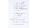
Fig 1 shows the basic layout of the aluminium clamp, photo 5. My procedure was first to saw roughly to size then deal with most of the milling operations. The opportunity was taken here to try out an industrial “roughing cutter”. These are characterised by what looks like a screw thread running up the body of the cutter.
For industrial applications they give high rates of stock removal. However the downside is that the surface finish has a series of fine grooves and it was therefore decided to take a finishing cut with a conventional end mill.
The two positions for the M6 stud and the cap screw were drilled and tapped, and that for the cap screw counterbored. It is worth checking the depth of hole for the stud carefully as if this is taken too deep then it breaks into the bore causing interrupted cutting as the final diameter is approached when boring.
As you are aiming for a close fit over the barrel, it is worth measuring the diameter carefully, mine came in at 1.115in., and turning up a gauge piece, which can then be used to test the bore diameter as it approaches finished size.
The work was then marked out and centre punched for the location bore, before being gripped in the four-jaw chuck for centring up, photo 6. It was then bored to fit the barrel after which it was then back to the mill to cut the slot with a slitting saw.
The steel clamp bar, was cut over length from 3mm plate, then folded, photo 7. Adding length gave a bit more to get hold of when folding. It was then cut back to size and filed to remove burrs. A 6.3mm clearance hole was then drilled for the location stud.
For the jaw stop, the copper strip was simply cut and folded, then the two holes punched 3/16in. diameter using a Roper-Witney hand punch. The positions of these were determined by measurement of the positions of the oil nipples. As mentioned, a piece of 3mm copper was added on by soft soldering, photo 8.
The original intention was to form a second clamp, but with the underside filed away a little to bring the brackets to a common level, this proved useful in adding to rigidity.
In use
Unlike the ML7, the Super 7 has a self-ejecting tailstock so that as the barrel is wound back close to its limit, the Morse taper is released. Most of my MT2 accessories have the usual tang, and these are ejected about 3/4in. before the limit. Thus for most of the time, the aluminium bracket may be left in place. Some centres have no tang, and to release these, the clamp has to come off as the barrel needs to be wound right back.
In any case, from a standing start, it should take only a minute or so to assemble the bracket plus jaw stop and then locate the calliper. It is quite an easy matter to align the bar of the calliper with the edge of the lathe bed by eye. The moving jaw is then pushed against the stop. It is then a newfound luxury to be able to move the drill to touch, press zero, and then drill accurately to the required depth without guesstimating from the barrel markings. The heading photo shows the brackets in place and the calliper clamped in position.
Advert
Enjoy more Model Engineer & Model Engineers’ Workshop Magazine reading every month. Click here to subscribe.