VFD and screwcutting

Advert

VFD and screwcutting

Home Forums Help and Assistance! (Offered or Wanted) VFD and screwcutting

Viewing 19 posts - 1 through 19 (of 19 total)
  • Author
    Posts
  • #433387
    Mike Henderson 1
    Participant
      @mikehenderson1

      Hi,

      I'm looking at fitting a VFD and 3 phase motor to my Speed 10, partly for the usually quoted reasons and partly because I feel like upgrading it a bit!

      However, I have a query before splashing out. It is a metric machine and, unlike the 7 Series, it has a metric leadscrew of 3 mm pitch. This renders the thread dial indicator on the rack feed shaft ineffective, as it also is for imperial threads. My usual habit is to leave the half nuts engaged and to stop the motor at the end of the thread , withdraw the tool and reverse back to the start.

      So far, no problem. As I understand it, the VFD will feature a ramp-down deceleration time which seems to be independent of the set frequency.

      Can anyone advise if this is likely to pose a problem when screwcutting, especially up to a shoulder? I cut a roughly equal mix of metric and imperial threads and usually do so in the slowest direct speed, i.e. not using backgear.

      Thanks in anticipation,

      Mike

      Advert
      #33469
      Mike Henderson 1
      Participant
        @mikehenderson1
        #433388
        Ian Parkin
        Participant
          @ianparkin39383

          Mike

          it may be a problem up to a shoulder but the ramp down is a product of the frequency set so at 10hz the motor will ramp down quicker than at 50hz

          however you can set the ramp down to 0% or wire in a quick stop button for use whilst thread cutting and use the usuall ramp down (stop) button for normal work

          #433391
          Clive Foster
          Participant
            @clivefoster55965

            Ramp down times on decent quality VFD units are very consistent, certainly better than (normal) human reactions, so it shouldn't be an issue. You already have motor coast down to cope with. Ramp down time need not be much greater. 5 seconds should be ample, I'd probably try 3.

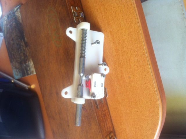
            Consider making a bed stop with a sprung loaded microswitch inside. Connect the switch to the inverter controls and set the stop so the switch operates at the end of the thread. No more worries about stopping the motor in time.

            Something like this inside the stop block would probably work :-

            photo 3.jpg

            That one was stolen from the lid mechanism of a spin drier rusted out after 20 odd years so the concept is reliable.

            Clive

            #433408
            Mike Poole
            Participant
              @mikepoole82104

              I would have a look at the braking features before making a decision on a VFD. A short ramp may be enough to give you what you need but some drives can use DC injection type braking which can be quite brutal. Some drives will need an external resistor to use the shortest ramps. I think that the ML 10 will probably only need the standard drive to give you the performance you want as it doesn’t have a large inertia to control. If you don’t mind fiddling then you could probably shorten the ramp at low speeds but it may trip with a heavy job or fast speed.

              Mike

              #433410
              Pete Rimmer
              Participant
                @peterimmer30576

                Any decent VFD will stop from the spindle screwcutting speeds in less than a turn especially in back gear, and less than quarter of a turn isn't hard to achieve if you're running up the a shoulder. Of course, having a VFD can let you increase your screwcutting speeds but another benefit is that you can use the speed control to back the speed right down as you approach the shoulder so that the stop is almost instant.

                An external resistor is used to prevent the DC bus going over-voltage when braking. Easy to fit, easy to set up too, and pretty cheap.

                It's difficult to find any reason not to use one TBH.

                Edited By Pete Rimmer on 15/10/2019 13:30:10

                #433411
                old mart
                Participant
                  @oldmart

                  The Schneider VFD which I bought for the mill has a default ramp up and down time of 3 seconds, this can be changed, but I don't know if changing it to 1 second stop would act like a brake. Another option is coast to a stop. Fitting a reversing switch option allows you to throw the motor into reverse.

                  Three phase motors come with different numbers of poles, from 2 upwards. These are the common types in small motors.

                  2 pole 3000rpm                                                                                                                                                                  4 pole 1500rpm                                                                                                                                                                  6 pole 1000rpm                                                                                                                                                                  8 pole 750rpm

                  I bought a 6 pole which is listed at 935rpm, and have set the VFD to run from 25Hz to 75Hz (467-1402 rpm), which in conjunction with the belt pulleys, gives a useful spread. Lower frequencies lower the power of the motor, 25Hz loses 50%.

                  Edited By old mart on 15/10/2019 13:46:17

                  #433412
                  Pete Rimmer
                  Participant
                    @peterimmer30576
                    Posted by old mart on 15/10/2019 13:32:56:

                    The Schneider VFD which I bought for the mill has a default ramp up and down time of 3 seconds, this can be changed, but I don't know if changing it to 1 second stop would act like a brake.

                    That's exactly what it does, anything that stops the motor quicker than coasting is braking the motor. Your two considerations are that you don't overload the DC bus and you don't spin off the chuck.

                    #433413
                    Anonymous

                      Slowing a motor is essentially a problem of getting rid of the energy in the motor, both mechanical and electrical. If the VFD goes to zero frequency, ie, no drive, the motor will slow as energy is lost to friction. However, the motor also acts a generator which may lead to the DC bus over-volting. So a braking resistor is added to dissipate the regenerative energy and prevent over-volting. This also has the effect of slowing the motor down more quickly. On larger and/or more expensive VFDs the braking resistor can be dispensed with and DC injection braking used instead. In this case the inverter applies a DC voltage to the motor in a sense that causes a DC current to flow in the windings that opposes the current flowing due to the initial magnetic fields in the motor. While this can stop the motor very quickly it cannot be used for long. As the motor slows the DC current will rise, eventually being limited solely by the winding resistance, which will lead to overheating.

                      Andrew

                      #433441
                      DC31k
                      Participant
                        @dc31k
                        Posted by Pete Rimmer on 15/10/2019 13:29:31:

                        …another benefit is that you can use the speed control to back the speed right down as you approach the shoulder so that the stop is almost instant….

                        And if you had a sliding potentiometer attached to the bed, you could do this automatically, in a similar manner to the trip mechanism on dog clutches used for screwcutting.

                        #433449
                        jimmy b
                        Participant
                          @jimmyb

                          I've just fitted a VFD and 3 phase motor to my Chester Crusader.

                          Screw cutting has been transformed!

                          I have left mine on the supplied settings and have found it to better to control than previously.

                          Good luck!

                          Jim

                          #433455
                          Mike Henderson 1
                          Participant
                            @mikehenderson1

                            Hi,

                            Thank you all for the advice and information. I have a lot to think about but, at the moment, feel it is worth going ahead.

                            To colour-in the picture a bit, I'm thinking of one of the Newton Tesla packages, in part because it it a one-box solution and in part because the inverter arrives ready programmed for the motor supplied.

                            I have, in the past set up a few inverters but they were vastly simpler than today's offerings. I downloaded the manual for the VFD that Newton Tesla supply and the number of parameters that can be set if bewildering – on a first read through, I didn't understand a lot of the jargon.

                            I realise that buying into the package carries a cost implication, but feel this is worthwhile for me. Motor and inverter as separates are cheaper but there is the add on cost of the control buttons, rheostat. enclosure and interconnections, plus the time and effort to source these and make a respectable job of assembly. I don't have a great deal of hobby time and prefer to spend it making models or other projects, rather than means-to-an-end tooling.

                            As supplied, the frequency limits are set to give 185 to 1800 rpm with a 4-pole motor and I will probably end up increasing the frequency somewhat, to provide a higher top speed as I do quite a lot of work on small brass parts. a good read of the manual beckons! I imagine the limiting factor on the speed may well be the plain bearing countershaft. I don't plan to exceed the safe speed for the chucks.

                            I must thank Clive, in particular, for his suggestion of a microswitch bedstop and DC31k for the suggestion of a sliding resistor stop to reduce speed as the shoulder approaches. Finally, a special thank you to Pete Rimmer for pointing out that the speed can be varied on-the-fly. That is probably obvious to those who have inverter fitted machines but which I had totally overlooked.

                            I realise opening the box and altering settings will probably invalidate the excellent 10-year warranty on the inverter, let alone adding extra switches but I would be happy to take a chance if the initial settings didn't meet my needs. Initially, though, I'll call Newton Tesla and enquire whether they are willing to customise the settings.

                            Thank you all, once again. What an excellent place this forum is.

                            Mike

                            #433487
                            Clive Foster
                            Participant
                              @clivefoster55965
                              Posted by DC31k on 15/10/2019 18:03:28:

                              Posted by Pete Rimmer on 15/10/2019 13:29:31:

                              …another benefit is that you can use the speed control to back the speed right down as you approach the shoulder so that the stop is almost instant….

                              And if you had a sliding potentiometer attached to the bed, you could do this automatically, in a similar manner to the trip mechanism on dog clutches used for screwcutting.

                              DC31k

                              The speed adjusting potentiometer in the stop is an interesting idea. What do you see as the advantages over using a simple stop switch and relying on the ramp down of the VFD to bring things to a stop. Obvious one is that it allows you to use a different braking profile for screw cutting / feed to a shoulder than the normal stop ramp down.

                              Mike

                              I planned to use a switch actuator based on the one in my picture with a 6 position turret type bed-stop head having a short spring loaded slide incorporated in the mounting clamp. As is so often the case it got over designed with built in micrometers for easy setting (gotta do something with those half inch travel heads in the useful box) and interchangeable length rods. So its 15 years on its still at back of envelope stage and I'm still doing fine with the dumb 6 way turret I've had for the last 30 – 40 years!

                              Clive

                              #433528
                              Mike Henderson 1
                              Participant
                                @mikehenderson1

                                Clive,

                                I find the sliding potentiometer idea an interesting concept and worth bearing in mind, however, your bedstop switch is much simpler to execute and will be my first approach once the VFD is up and running.

                                My mentors, years ago, before that word was in common usage, taught me to believe that the simpler the solution the better, so long as it achieved the desired result. I have tried to stick with this in career, life and hobbies.

                                I have downloaded a more succinct manual for the VFD, written with more English and less jargon. It is much easier for me to digest and it is clear from this that the ramp-down time is proportional to the speed setting or, perhaps more correctly, to the frequency setting. The comprehensive manual I was reading first provided so much complexity that this was, to me at least, obscured.

                                Time to flash the plastic, me thinks.

                                Mike

                                Edited By Mike Henderson 1 on 16/10/2019 15:20:46

                                #433532
                                Michael Briggs
                                Participant
                                  @michaelbriggs82422

                                  Hello Mike,

                                  I did my own VFD setup which is similar to the Newton Tesla setup except that I have a separate jog button and an emergency stop that isolates the drive. I use the jog button for screw cutting and tapping, works well for me, the drive stops as soon as you release the button.

                                  If a stop limit switch is triggered by the carriage then it will probably have to either be taken out of circuit or mechanically de-activated to allow you to reverse the drive back to the start of the thread.

                                  Michael

                                  #433541
                                  jimmy b
                                  Participant
                                    @jimmyb

                                    I went down the Newton Tesla route.

                                    Expensive, but no regrets!

                                    Jim

                                    #433558
                                    Andrew Evans
                                    Participant
                                      @andrewevans67134

                                      I looked at Newton Tesla, then got a 2nd hand Mitsubishi VFD (same as the one used by Newton Tesla), a quality 2nd hand 3 phase motor and a prewired control box off eBay for £30 – saved myself about £200 and got the same result. I had to program the VFD but that is pretty easy once you get the hang of it and read the manual.

                                      If you work out how to program the VFD it then becomes obvious how to wire in extra microswitches and tune it to the speeds that suit your lathe and the work you are doing.

                                      Its a big improvement.

                                      Edited By Andrew Evans on 16/10/2019 17:46:47

                                      #433578
                                      DC31k
                                      Participant
                                        @dc31k
                                        Posted by Clive Foster on 16/10/2019 10:06:27:

                                        The speed adjusting potentiometer in the stop is an interesting idea. What do you see as the advantages over using a simple stop switch and relying on the ramp down of the VFD to bring things to a stop. Obvious one is that it allows you to use a different braking profile for screw cutting / feed to a shoulder than the normal stop ramp down.

                                        The suggestion of an automatic pot to ramp down the speed was an extension of Pete Rimmer's observation that a VFD can be used to back the speed down.

                                        It seems to me that something fixed on the machine that is actuated by the movement of the machine would be more repeatable than the user twiddling a knob. With a human in charge, the start of the twiddling and the speed of twiddle are rather variable.

                                        As to any particular advantage, can I table this for discussion? It may be easier to set up or adjust this form of control: set the carriage in the position you want it to to stop at; slide the control mechanism until it is telling the VFD to output zero Hz; slide the whole switch/control assembly along the bed until it touches the carriage and secure in place.

                                        I think in this way you could get very precise and very repeatable positional control of tool relative to workpiece.

                                        With the microswitch, you have to position the assembly some unknown distance before the stopping point to allow for the ramping and then judge the exact switching point of the switch (clamp it in place on the 'c' of the click and not the 'k&#39. As you showed in the picture, the mechanism needs to have over-travel capacity in it. The tumble dryer one is an excellent source.

                                        I am slightly concerned about comments on ramping that the time is independent of the speed. So if you have a five second ramp time, it takes 5 seconds to stop whether you are doing 20mph or 200mph. One does not need a seatbelt; the other possibly requires a G-suit to prevent injury.

                                        I also need to think a bit if thread pitch being cut influences the VFD ramping method. Say we can control to 25% of a turn. The distance moved in 25% of a turn is quite different between 4TPI and 40 TPI.

                                        Maybe time for some experiments: set up a dti on the back of the carriage and run into the microswitch at various speeds and pitches and see if carriage stopping position varies.

                                        #433590
                                        Michael Briggs
                                        Participant
                                          @michaelbriggs82422

                                          I have had a look at the literature for Rockwell drives, the acceleration and deceleration times are defined as the time it takes to accelerate from rest to maximum speed or decelerate from maximum speed to rest, makes sense to me. Other manufacturers may have different ideas.

                                        Viewing 19 posts - 1 through 19 (of 19 total)
                                        • Please log in to reply to this topic. Registering is free and easy using the links on the menu at the top of this page.

                                        Advert

                                        Latest Replies

                                        Viewing 25 topics - 1 through 25 (of 25 total)
                                        Viewing 25 topics - 1 through 25 (of 25 total)

                                        View full reply list.

                                        Advert

                                        Newsletter Sign-up