New lathe arrived today : The ongoing saga

Advert

New lathe arrived today : The ongoing saga

Home Forums Beginners questions New lathe arrived today : The ongoing saga

Viewing 25 posts - 501 through 525 (of 972 total)
  • Author
    Posts
  • #207075
    Ketan Swali
    Participant
      @ketanswali79440

      Hi Brian,

      The good news is that it is a 55mm register = most Chinese 80mm chucks, 3-Jaw and 4 Jaw, and you have a way to mount three bolt or four bolt, so all is well on this front.

      A SIEG Mini-Lathe face plate at 55mm register, which is good, but 160mm diameter, but not suitable for your application.

      Your manual says 140mm swing (I think), but I am not sure about this. Can you measure from the centre of your spindle to the angled part of the motor cover and advise the measurement?

      You may be able to use a 100mm blank backplate for a SIEG mini-lathe, which has a 55mm register. Instead of slots, or holes, you could drill and tap it in places for mounting. You can discuss this with others.

      Ketan at ARC.

      Edited By Ketan Swali on 08/10/2015 13:37:11

      Advert
      #207076
      Ketan Swali
      Participant
        @ketanswali79440

        If you decide to consider the backplate route, try to source something like 040-060-10200 C3 100mm Backplate – Plain – Steel, which you can find on this page: http://www.arceurotrade.co.uk/Catalogue/Chucks/Lathe-Chuck-Backplates

        The backplate has a 55mm register, and it is drilled and tapped in the 3 holes. The three holes will locate in the same place as your existing 3 holes (PCD) where your chuck was mounted – hopefully. The front is blank enabling you to drill/tap, or put in T slots, but please discuss with Hopper and others on here before you consider this route.

        Ketan at ARC.

        Edited By Ketan Swali on 08/10/2015 13:54:01

        #207080
        Ketan Swali
        Participant
          @ketanswali79440

          Possible Plan B, depending on the measure from the centre of the spindle hole to the chamfered edge of the motor housing.

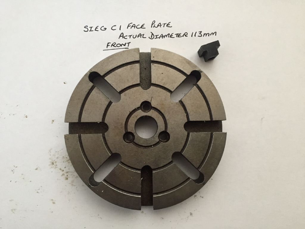
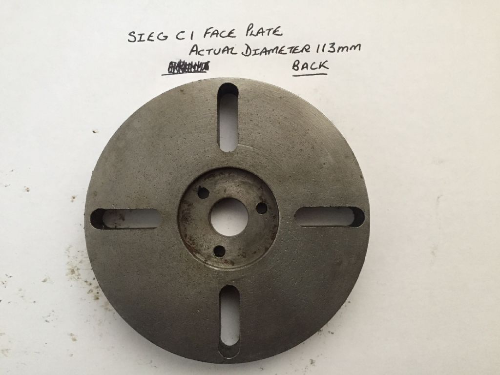
          SIEG C1 lathe faceplate is 113mm diameter (even though it is stated as 110mm, which is nominal diameter): http://www.axminster.co.uk/axminster-sieg-c1-110mm-faceplate

          ARC does not sell it, and nor does Ausee. Hope Brian can find in Australia, if he decides to go down this route and if someone is able to assist him for the modifications needed. It may be a route which Brian might want to consider if the faceplate diameter fits his machine.

          Please see these pictures:

          img_2650.jpg

          img_2651.jpg

          – Current register on the back is 40mm. This needs to be opened up to 55mm

          – From the front, the four through slots could be used to mount the face plate to the four holes in the spindle flange (66mm PCD hopefully), using screws to suit, may need to countersink?

          – The T-slots are 8mm wide, which will accept M6 T Nuts.

          Ketan at ARC.

          #207081
          Neil Wyatt
          Moderator
            @neilwyatt

            Ketan – is there a possibility that the 40mm register would fit directly to Brian's spindle if his 55mm register backplate was removed?

            Neil

            #207084
            JasonB
            Moderator
              @jasonb

              Neil, it would need redrilling to take 4 fixings and they may come a bit close to the existing 3 in the Axi faceplate

              If brian is going down the route of bolting on a faceplate to te spindle for modification may as well get a billet of aluminium drill, tap and bolt to spindle then cut the recessed 55mm register. The Ali one will be easier for him to drill and tap.

              #207085
              Ketan Swali
              Participant
                @ketanswali79440

                Not sure Neil.

                Looking at Part 16 – Exploded diagram 8.2 in the manual, suggests that it has mounting holes for 3 hole and 4 hole mounting. Brian will need to remove the current backplate to check PCD, hole arrangement/s and spindle flange diameter.

                The same diagram also shows the backplate only having three holes for mounting 80 mm chucks, where as Brians picture shows more, enabling mounting of Chinese 80mm 4-Jaw independant chucks which have four bolt mounting.

                Alternatively, Jasons suggestion with Ali also sounds good.

                Ketan at ARC.

                #207128
                Brian John
                Participant
                  @brianjohn93961

                  The distance from the spindle hole centre to the motor housing is 60mm so a 100mm face plate is a possibility. I have been thinking about this last night. What are the disadvantages of using some sort of face plate with a 16mm round bar welded to the centre attached and then mounted in the lathe chuck ? Does this not give good results ?

                  #207135
                  JasonB
                  Moderator
                    @jasonb

                    It won't be much different to your large flywheel bolted to the 16mm bar that you made the mandrel out of eg flexing due to larger overhang than if it were bolted to teh spindle nose and small shaft to large dia ratio

                    You will also have to face it true each time as the 3-jaw will not hold it true and you possibly don't have 50mm of cross slide travel to do it in one go.

                    #207136
                    Brian John
                    Participant
                      @brianjohn93961

                      Okay, so a face plate it must be then. My chuck is not easily removed or put back on ; the fit is very tight. Are all lathe chucks like this ?

                      I had a look at the adjustment screws on the cross slide today by removing one of them. The ends are flat ie. they are neither pointed nor rounded.

                      #207167
                      Hopper
                      Participant
                        @hopper
                        Posted by Brian John on 09/10/2015 07:37:07:

                        Okay, so a face plate it must be then. My chuck is not easily removed or put back on ; the fit is very tight. Are all lathe chucks like this ?

                        I had a look at the adjustment screws on the cross slide today by removing one of them. The ends are flat ie. they are neither pointed nor rounded.

                        Hi Brian, if the cross slide uses a conventional gib strip with dimples drilled in it for the screws to sit in, rounded ends on those screws will work much much better than flat. Pointed tend to wear grooves in the gib strip with use where rounded do not.

                        If you can get hold of one of those Sieg 103mm diameter face plates, we can always put it up in my old Drummond and enlarge the register diameter to fit your 55mm backing plate. Or as pointed out also, a disc of ally could also be machined up to fit.

                        #207234
                        Brian John
                        Participant
                          @brianjohn93961

                          Thank you Peter, I will have a look at ebay later today to see what is available. Last time I looked everything was too big or too small. This one might work but I have to double check a few things :

                          **LINK**

                          I bought an Ozito 6 inch bench grinder yesterday. I will order a green wheel from Blackwoods on Monday. The 100 grit should suffice as I only want to touch up the brazed carbide tips.

                          #207247
                          Hopper
                          Participant
                            @hopper
                            Posted by Brian John on 09/10/2015 22:49:17:

                            Thank you Peter, I will have a look at ebay later today to see what is available. Last time I looked everything was too big or too small. This one might work but I have to double check a few things :

                            **LINK**

                            I bought an Ozito 6 inch bench grinder yesterday. I will order a green wheel from Blackwoods on Monday. The 100 grit should suffice as I only want to touch up the brazed carbide tips.

                            Yes that faceplate looks like it would do the job. Easy peasy to machine a 55mm register recess on the back and if necessary drill countersunk bolt holes in the right positions.

                            You will be able to touch up your drill bits on that grinder too. Good stuff.

                            #207256
                            Brian John
                            Participant
                              @brianjohn93961

                              I replaced the chuck and closed up the jaws. This enabled me to make a more accurate measurement of the distance from the centre of the chuck to the motor housing = 62mm. So a 120mm faceplate would be the maximum size. That one on the ebay link is 4 3/8 inch = 111.25mm so there is plenty of room there.

                              1. Is it worth buying the clamping kit at the same time if they offer free postage ?

                              **LINK**

                              2. Regards a spindle handle : I have been wondering what could be utilised to make a spindle handle rather than trying to make one from scratch. Would something like this give enough leverage ?

                              http://www.ebay.com.au/itm/NEW-Universal-Aluminium-Car-Auto-Vehicle-Billet-Window-Winder-Crank-Handle-Kit-/400957243830?hash=item5d5aea01b6

                              Edited By Brian John on 10/10/2015 08:07:52

                              Edited By Brian John on 10/10/2015 08:09:00

                              #207260
                              Ketan Swali
                              Participant
                                @ketanswali79440
                                Posted by Brian John on 10/10/2015 08:05:15:

                                1. Is it worth buying the clamping kit at the same time if they offer free postage ?

                                **LINK**

                                YES, for general use. You may have to make additional clamping elements for your specific application.

                                Ketan at ARC.

                                #207261
                                Michael Gilligan
                                Participant
                                  @michaelgilligan61133
                                  Posted by Brian John on 10/10/2015 08:05:15:

                                  2. Regards a spindle handle : I have been wondering what could be utilised to make a spindle handle rather than trying to make one from scratch. Would something like this give enough leverage ?

                                  .

                                  Brian,

                                  Given the small size of the lathe; I would be tempted to use a handwheel instead … it gives much more control than a 'crank handle'.

                                  MichaelG.

                                  #207268
                                  JasonB
                                  Moderator
                                    @jasonb

                                    Or just grab hold of the chuck, its worked for me for 30 years

                                    #207269
                                    Brian John
                                    Participant
                                      @brianjohn93961

                                      I have been using the chuck method….what a pain ! It is too slow. A spindle handle is a much better idea.

                                      I like the  hand wheel idea. What could be utilised to make this…old sewing machine flywheel perhaps ?

                                      Edited By Brian John on 10/10/2015 10:28:14

                                      #207294
                                      Brian John
                                      Participant
                                        @brianjohn93961

                                        Lots of useful hand wheels here. I will have a closer look tomorrow. 240mm diameter is the maximum size for this lathe ; a larger will not fit.

                                        http://www.ebay.com.au/sch/i.html?_odkw=100mm+hand+wheel&_osacat=0&_from=R40&_trksid=p2045573.m570.l1313.TR0.TRC0.H0.X200mm+hand+wheel.TRS0&_nkw=200mm+hand+wheel&_sacat=0

                                        Edited By Brian John on 10/10/2015 12:27:55

                                        Edited By Brian John on 10/10/2015 12:28:42

                                        #207383
                                        Ian S C
                                        Participant
                                          @iansc

                                          If you come across an old sewing machine, they often have a wheel about 150 mm / 6" dia, I used one as aflywheel on one of my hot air engines.

                                          Ian S C

                                          #207386
                                          ega
                                          Participant
                                            @ega

                                            Brian John:

                                            A suitable pulley can be converted into a handwheel with the addition of a handle. There is a photo of one in my album.

                                            #208048
                                            Brian John
                                            Participant
                                              @brianjohn93961

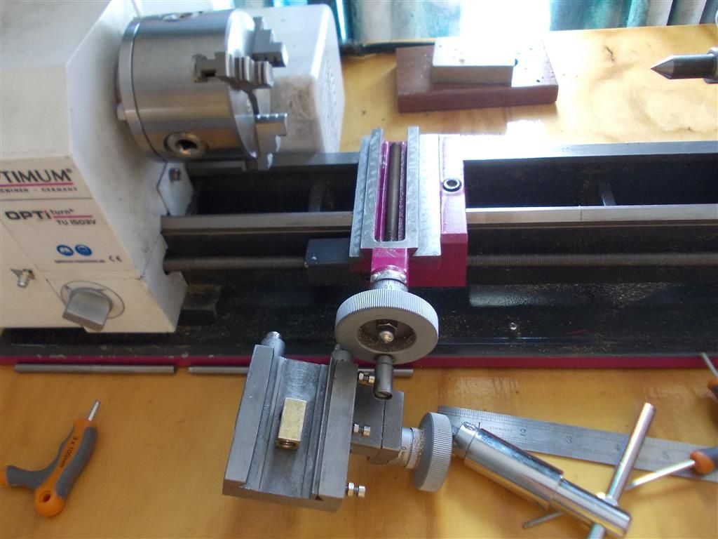
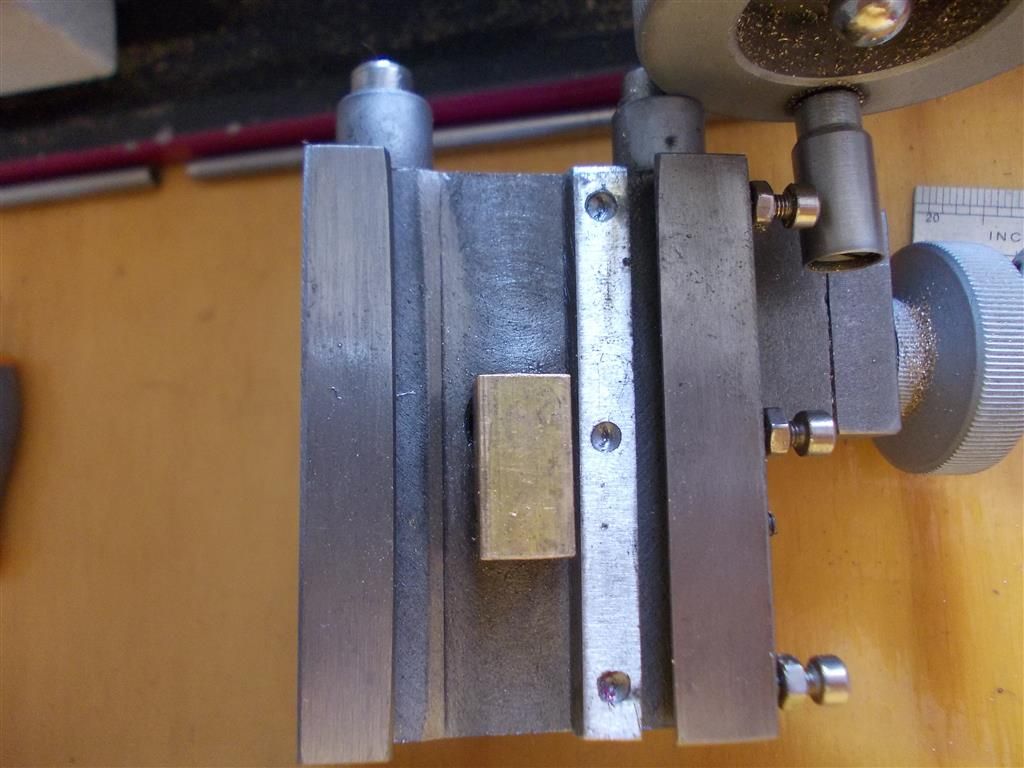
                                              I had a look at the cross slide today because it is really becoming a nuisance to have to adjust the gib screws whenever I move from the centre to the outer limit closest to me. I removed the back screen , undid the gib screws and unwound the cross slide until it slid completely out. The gib screws were flat so I filed a bit of a point on each one with the flat of a diamond wheel in the dremel tool. There was a rough edge around the dimples on the gib where they had drilled the dimples so I filed these flat to remove the rough edges. I removed all the swarf and oiled the moving parts.

                                              After putting it back together, it is a bit better then before but still not great. I am not sure what else can be done. I may have to live with it. I do not do up the lock nuts on the gib screws anymore. I need to be able to adjust them quickly depending on where the cross slide is ie. loosen them off when in the centre and tighten them up when closest to me.

                                              NOTE : the gib can only be fitted one way so no problem putting it back together incorrectly. I am still looking at ''dowelling the gib'' but I have to be honest here  in that I do not see how it helps. I  must be looking at it the wrong way !

                                              cross slide 3.jpg

                                              cross slide 4.jpg


                                              cross slide 5.jpg

                                              Edited By Brian John on 16/10/2015 08:20:05

                                              #208055
                                              mahgnia
                                              Participant
                                                @mahgnia

                                                Brian,

                                                It may just be the casting shape or the rounding of the machined edges, but the dovetail on the cross slide looks curved in those pictures, especially on the side away from the gib.

                                                Are you able to check for straightness?

                                                Andrew

                                                #208057
                                                Ajohnw
                                                Participant
                                                  @ajohnw51620

                                                  You could try the treatment mentioned on the Oz Taig pages Brian but don't use anything coarser than they suggest as that might make things worse. Why- from the photo's I can't see if the slides have been ground or just machined. In either cases there can be some degree of roughness to the surfaces – this will wear off much more quickly than the bulk area of the slide's surfaces leading to tight spots.

                                                  A common problem with earlier chinese machine was sharp edges on the male part of the dovetail and these fouling on the female part. There should be a narrow flat running along the sharp edge of the male half. Reason – it's rather difficult to ensure a dead sharp corner in the female part. The flat only needs to be say 1mm wide.

                                                  John

                                                  #208059
                                                  Brian John
                                                  Participant
                                                    @brianjohn93961

                                                    Mahgnia : yes, it does look very curved on the side away the gib. Might that explain everything ie. why it is much tighter in the middle ? I may take it off again tomorrow and have a closer look. I must admit that I did not see it because I was not looking for it. I had assumed that they could machine the edges in a straight line !

                                                    John : I assume that machined edges are machined in a milling machine. What are ''ground'' edges ?


                                                    Edited By Brian John on 16/10/2015 10:10:41

                                                    Edited By Brian John on 16/10/2015 10:12:50

                                                    #208064
                                                    mahgnia
                                                    Participant
                                                      @mahgnia

                                                      Brian,

                                                      If you have a good stiff straight edge, you will need to check the straightness on all the faces of the dovetail.

                                                      Checking the saddle dovetail for parallel would also be a good idea. You can use 2 short round pieces that fit against each side of the dovetail, and measure across them at several places. The more accurately round and parallel they are, the better.

                                                      We shouldn't jump to conclusions without testing. However, if the dovetail is not straight the gib strip and grub screws would be the only thing holding the cross slide and toolpost steady against movement under cutting forces. It might explain many of the issues you've had.

                                                      John's suggestion to check the top edges of the saddle dovetail for clearance to the cross slide dovetail is also very important. The gib strip would also need to be checked for the same clearance at both the top and bottom edges.

                                                      Andrew.

                                                    Viewing 25 posts - 501 through 525 (of 972 total)
                                                    • Please log in to reply to this topic. Registering is free and easy using the links on the menu at the top of this page.

                                                    Advert

                                                    Latest Replies

                                                    Home Forums Beginners questions Topics

                                                    Viewing 25 topics - 1 through 25 (of 25 total)
                                                    Viewing 25 topics - 1 through 25 (of 25 total)

                                                    View full reply list.

                                                    Advert

                                                    Newsletter Sign-up