Part one
Ok, so of those of you who have had the pleasure of knowing the Clarke CL430, one of the things that soon begins to bug pretty much everyone I've known with a CL430 is how slow it is to move, you dread having to move the table up and down between operations, once you're there it's fine but getting there soon gets the heart rate up and nobody likes to be worn out. (People should know the irony that one of the 20th centuries biggest promoters of exercise "life style" died of a heart attack).
So this lathe is just begging for a rack and pinion, well it got one, but it got it too late, and I suspect this was largely down in part on warco's effort to promote the lathe to serious metalmunchers, but getting hold of one of the WMT300/02 is as rare as hens teeth it seems.
So going down the best part of £800 for this monster you're feeling the urge to have a go yourself, but I think I walked before I could run, and underestimated just how much you need to consider before you can get this seriously going.
So step one has already been covered, we know we want a rack and pinion feed and we want it on a CL430, step two would be to survey the land, what are we dealing with, when it comes to fixing this thing on the machine.

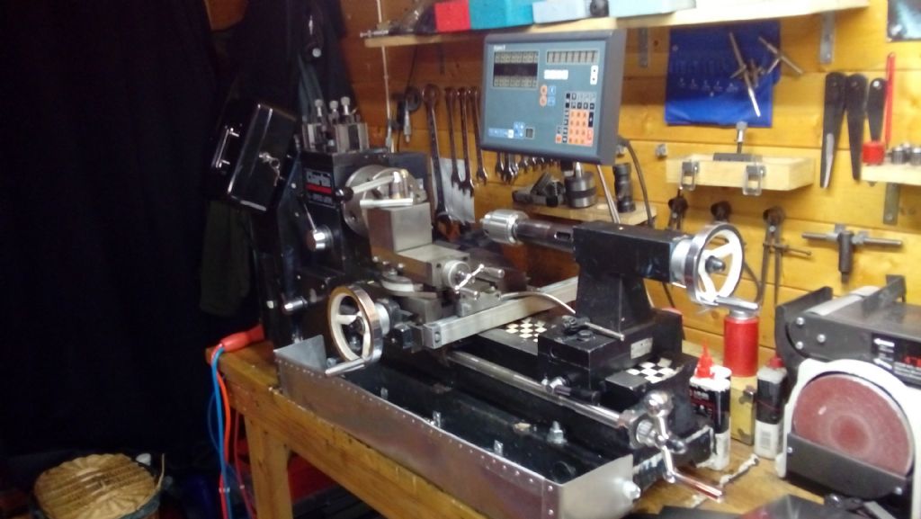
So this is a glance at my machine as it sits today. I'm part way through building an aluminium chip tray as you can see. But it's also got a few other differences to the original, vital i'd say. I couldn't actually fit the rack and pinion on this because the tray blocks it's original position for the moment, the rack itself has been removed(and now I've lost it) but It's really simple enough to explain, I bought a straight length of 1mm pitch rack bar with a pinion from ebay and drilled 3 holes along the length, to which "fixing posts" were attached, the base of the posts needed to be angled because I figured I had the most room to play about on the base of the lathe, (so the rack was upside) and the cast face of the base is slightly off parallel by a few degrees. This ran the length of the base of the bed once it was fixed.
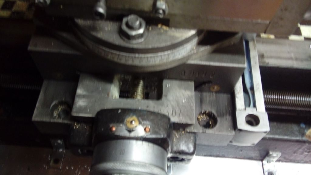
Down below you can see part of what formed the next problem, where the hell do you attach an apron to the lathe? I figured the easiest and strongest way to secure it would be to remove the cross slide, mark out drill and counter sink two M8 sunken socket screws into the apron, this was adequate because it meant that nothing in essence was truly damaged by my workings, and it could be removed if I I didn't want it anymore, my number one rule of modifications is don't do anything you can't undo to your equipment.
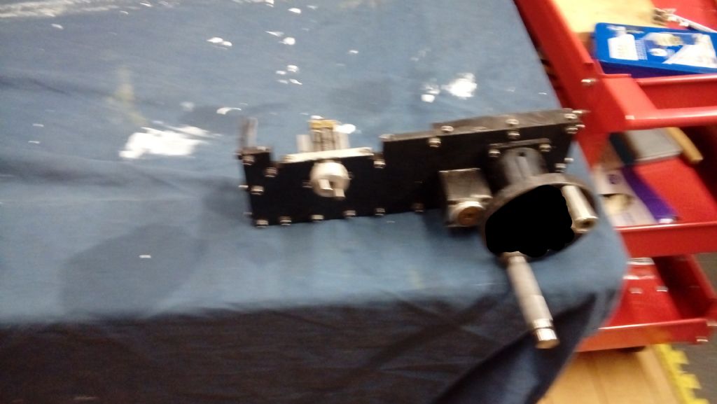
 So now we come to the exciting bit, what I actually made this apron out of. I used a 1/2" piece of T6 aluminium plate, some myford gears I deprived from a potentially caring and loving myford user on an ebay auction that nobody seemed interested in. (got a full set of myford change wheels). and some silver steel bar.
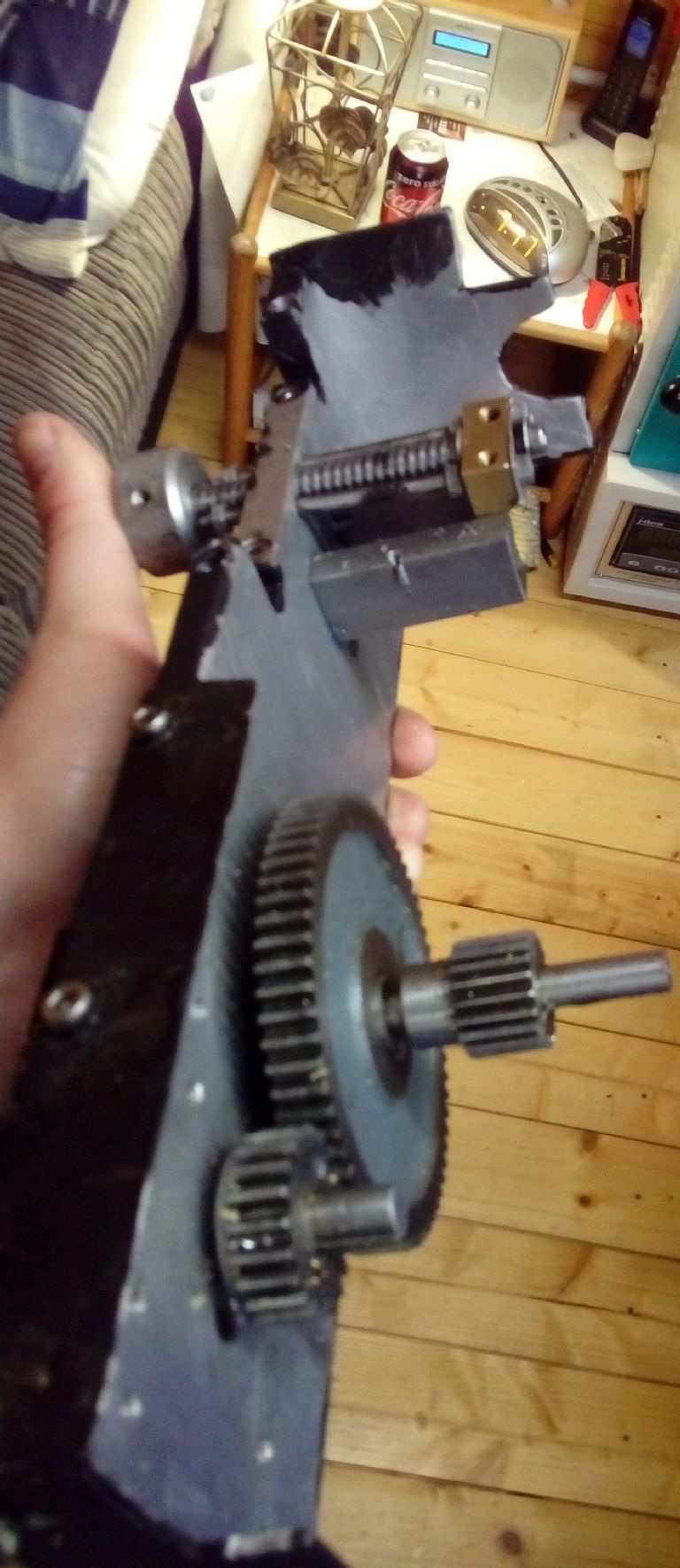
 And a close up of the workings.
 So I hope the gear train is fairly self explanatory what happens, I took the handwheel from another machine spare I had. That sits on some bearings. The little block you can see to the left of the traverse handle is a brass bearing block, because my pre-prototype proved 1/2" of support for the pinion shaft wasn't enough.
To the far left you can see the disgrace of my build which was a kind of "wrench on" half nut that was truly awful to use. You can ignore that but there isn't a lot of space under there and things were getting dire at that point, the half nut is a slitting saw cut piece of a feed nut from Clarke spares, don't break too many of them as they are a little pricy.
Gordon W.


 Never measured it before but suspect bigger lathes I have used move further and have much bigger hand wheels. The reason I can probably do it down to being told that I couldn't use power feed for a while during training. It's a 2 handed job just as using the other hand wheels are. One hand is needed to maintain the feed while the other one repositions and so on. I have seen video's of people doing one hand facing etc and find it odd that both me and a number of others found 2 hands is the best way especially if the slides are adjusted correctly. On the saddle the handle is for moving it and the rim is for the feed. I tried hand feeding a mini lathe – couldn't on this model as the wheel was too small or maybe the feed rate was too great. I intended to fit a larger diameter handle.

