Gary –
I take your point about TurboCAD's origins but without your previous experience, I take TurboCAD 19 Pro as it comes, without worrying about IMSI's software design methods. Though I would have appreciated a much better "Help" section!
It is fairly clear that TC reserves Layer 0 for itself, I think for construction-lines. It took me a long time to work out what Layers are and how to use them though. Unless I misunderstand him, D.A.G. Brown's generic guide to CAD says Layers can be used as an assembly-copy tool, giving tender axle-boxes as his example. I don't know if or how that works in TC though.
Thank you for the Viewport properties tip. TC allows any standard paper sizes, logically enough. Except it makes copying, scaling and printing a drawing from its original Model Space life about as hard as possible; muddled by several different paper-size lists of which some give only American ones.
Often I find its easier to copy and paste the drawing and to Hell with Viewport – but it still risks altered dimensions, and raising Hewlett-Packard's common, mystifying printer error-message about printing boundaries or something.
'
Certainly right about climbing a steep learning-curve; though I recall reading that a +ve-going parabolic arc in any learning means little progress at first then accelerating advancement! Not harder and slower but easier and quicker learning; having grasped the principles. dl / dt and all that. My curve follows no known mathematical law and often dips, reaching only foothills to inaccessible summits. Besides, as a poor climber with an unreliable head for heights (as would aver any of my caving friends of over 40 years)…. as in reality so in metaphor.
'''''
Nicholas –
Thank you.
I am not trying to force 2D restrictions on 3D. I know they are very different, and that a 3D design model is not merely pictorial. It forces restrictions on me, stopping me from doing what it lets its expert users do: design complex assemblies by 3D "models" that then become the source of the parts drawings.
I recognised the isometric modelling that CAD can give before opting to buy it. As well as all the other advantages, I wanted to be able to create isometric views of parts and complete assemblies. At the time I did not know if you can take off elevations for workshop use. I now know you can, but not how.
You refer to "parameters" for copying repeated parts – referring to a method specific to the CAD programme you use? The word is not in TurboCAD, but TC probably has equivalents much more efficient than the way I operate it.
I know what an expert CAD user can do, but I need be realistic about what I can learn. Your engine is perfectly possible in TurboCAD, but reaching that skill level is not possible in me.
So I am asking advice to help me judge if I might use CAD to better advantage by using a different make, easier to learn.
In any case, I cannot use SE unless and until I install Win-10; but I do not know what problems that will create.
+++
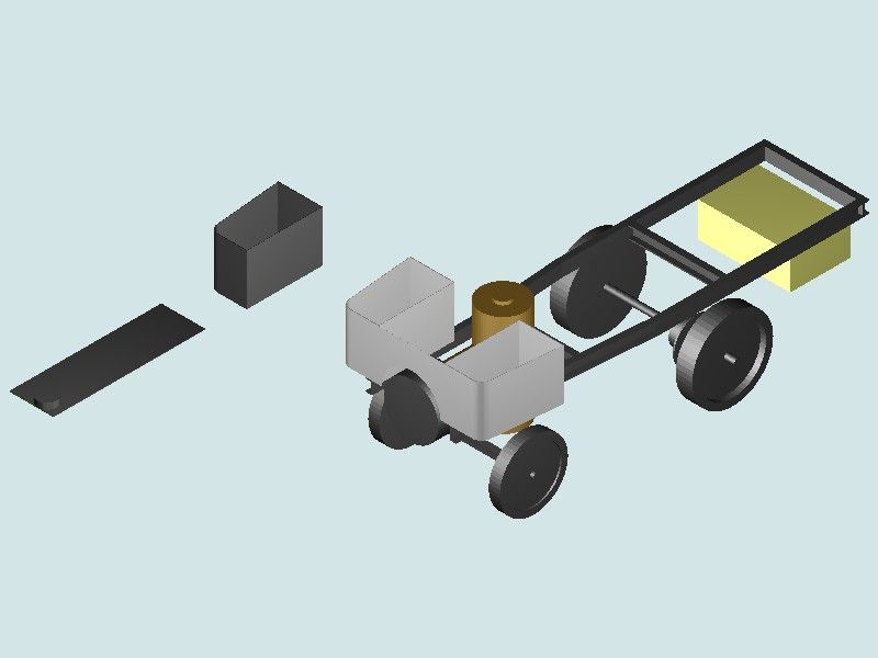
The drawing below is probably the last isometric CAD attempt I have made so far, and many months ago.
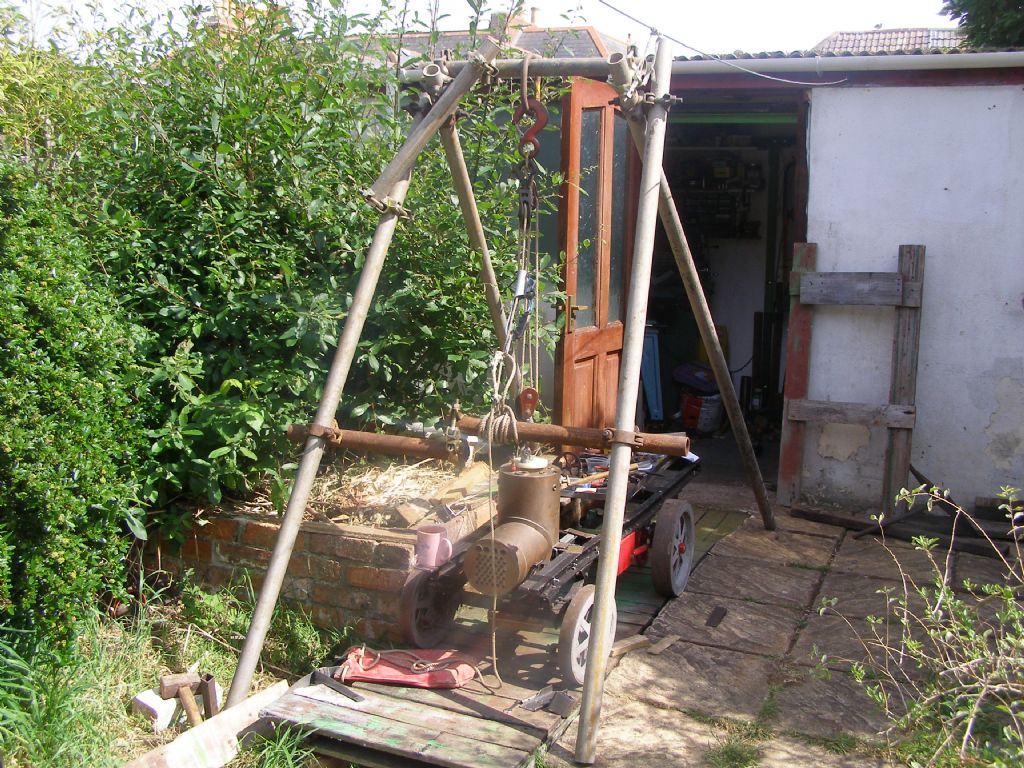
It is a general view of the 4" scale steam-wagon I have been taking far too long to make. There are no drawings for it, just a few old advertising photographs from 1908. This drawing reached my CAD skill limit, but despite parts removed, the construction stage is roughly that of the photo below it.
I took that when trying to design the boiler-mountings I made eventually to a rough pencil sketch and bits of steel clamped to the chassis. The red bit in the photo is tentatively the outer plate for the transmission assembly.
The drawing's two floating bits are a bunker and its floor, extended as the footplate. I took many attempts to draw that sub-assembly as neither a solid block (nowhere for the coal) nor lacking a floor (chassis rail visible in plan, the coal landing on the ground).
The brown cylinder is the firebox, the boiler shell being a T-piece standing on its side. The wheel discs are not really solid but pairs of rose-pierced plates. The yellow block represents the water-tank (brass). The rear axle is correct by dimension but looks too far forwards. The disc behind the wheel is the differential, converted from a car unit to traction-engine pattern with through and cannon shafts, and fitted with chain sprocket
I could have added the seats (two rectangular boxes) and symbolised the engine (another box, between the seats and behind the boiler). Detailing the wheels, adding the Ackermann steering-gear, springs etc – out of the question. All that lot is nearly as far as the vehicle itself has progressed.
This drawing conveys far less than a photograph of the made parts. As a TurboCAD 3D model – merely an exercise; scrappy, unfinished, best deleted. As a design drawing – dimensionally right but useless. Its only value is as a self-assessment of ability.
Experimenting though, I was surprised to find that TurboCAD will dimension a scanned photograph – but 2D only so useable only on planes perpendicular to the view. Nevertheless I used this to obtain some approximate dimensions for the engine-case.


