This article originally appeared in Model Engineers’ Workshop issue 128, August 2007
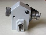
Owners of the Unimat 3 will know that there is no problem removing the drive belt from the auto-feed drive pulley. No doubt many like myself, will also, flip the belt off the auto-feed pulley and leave it to trundle around on the lathe mandrel, rather than take the trouble to remove the lathe drive belt and pulley, whenever the attachment is unlikely to be used for any length of time. Replacing the belt when required however is much more of a fiddling task, made even more difficult, by the pulley guard of the auto-feed.
After seeing a tool as supplied with a small vacuum cleaner, for replacing its belt, it was thought that something similar might also be made for the auto-feed. This proved to be unsatisfactory as apart from not being able to see what one was doing, there was also insufficient room within the lathe pulley housing to manoeuvre the tool. After a little thought, it was decided that rather than have a separate tool, perhaps the tool could become an addition to the pulley on which the belt was to be placed. The result being, that now the belt can be fitted by feel, with no tool to lose or fiddle about with.
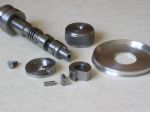
At the rear end of the drive pulley worm-gear shaft, is an attachment similar to a snail-cam, which seems to be an apt title for this item. When the drive belt is to be fitted, it is guided with the finger onto the hook of the snail-cam whilst the knob is being turned. As turning continues, more of the belt is collected and in turn drops into the groove of the drive pulley. For turning, a knob is fitted to the front end of the shaft and as this will be revolving whenever the lathe mandrel is turning and the belt is attached, a clutch has been incorporated within the knob. When the shaft is revolving, the clutch is disengaged and the knob can, for example, be held safely with a minimum amount of resistance. Turning the knob when the belt is to be fitted, will allow the clutch to engage and give a positive drive to the worm-gear shaft and so to the snail-cam. If the individual is not quite so safety conscious, then perhaps the clutch could be eliminated and a smoother knob that might not cause injury fitted instead.
Remove the auto-feed from the lathe and under the part of the casting next to where the lead-screw fits, there is a small grub screw. Carefully remove the screw followed by a spring and a steel ball. This will save you from wondering what it was that flew across the workshop when the next items, the cover and actuating knob are removed. Below and at right angles to the worm-gear shaft is a retaining pin, which should be punched through from the outside of the housing. Remove the worm-gear shaft and clean off the grease.
My own lathe has a saddle stop fitted under the headstock, with a stop-rod extending past the auto-feed attachment, so it was necessary to turn some of the auto-feed drive pulley down so that the snail-cam would not foul against the stop-rod. With the worm-gear shaft set in the lathe chuck, drill and tap each end for 6ba or similar size screws.
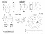
Starting with a 6mm length of 3/4in.dia mild steel, face off both ends in the chuck and drill through No 32, then countersink. With a boring tool, remove the centre to a depth of 4.5mm and a diameter of approx 12mm. Remove the piece from the chuck and set it sideways in the milling vice and using a 3mm end mill, cut the slot for the forming of the hooked portion of the snail-cam. Secure the cam to the worm-gear shaft, then with the shaft mounted in the lathe, turn down the cam to match the diameter of the pulley.
Using a small hacksaw and files or whichever method you prefer, cut and finish the upper edge to form a spiral, taking up the full circumference, except for a short parallel length where the hook will be shaped. Reassembly of the auto-feed, means that except for the spigot which is of a small enough diameter to pass through the casting, the other components must be made removable and so the centre for the clutch is keyed to the spigot. With the clutch fitted over the spigot, a hole is drilled in the two parts, a piece of rod is secured to the spigot and the clutch made to slide over it. When finally fixing the spigot, the screw or studding will need a thread sealer to prevent it being unscrewed when the knob is being turned anti-clockwise. Also, leave enough room for the screw that holds the knob in place.
There is probably some calculation for the dimensions of the clutch assembly, so the measurements arrived at are most likely by chance, but as they work successfully, what does it matter. A piece of mild steel is used for the clutch roller. Silver steel was tried but not did appear to release quite so freely. Mill the clutch centre, to the same depth as the diameter of the roller, then draw the cut-away portion on a file, until the knob, which is also the other half of the clutch, with roller included, turns freely in a clockwise direction. Turning the knob anti-clockwise should, almost immediately, cause the roller to wedge in the cut out and turn the worm-gear shaft. There will be times when the clutch will be in a position where the roller will not ‘bite’ and extra turning of the knob will be required. Fitting a second roller is the probable cure, but these occasions are few and it hardly seems worth the extra work, together with the possibility that the clutch may not release quite so freely. A countersunk screw, which tightens against the screw that holds the spigot to the worm-gear shaft, keeps the knob in place and is just of a length to allow the knob to turn clockwise, without turning the worm gear. With everything completed, replace the shaft and renew the grease in the auto-feed attachment before replacing the cover etc.
Having solved the problem of re-fitting the belt, somewhere to keep it when it is not in use would be better than leaving it to trundle around, as mentioned earlier, so a home for it was devised. My lathe has been modified with an alternative motor and drive arrangement to the one that was supplied when purchased and unfortunately the pulley cannot found, but from the diagram in the machines manual, there appears to be nothing that would prevent the same holder from being fitted to an unmodified machine.
Basically the holder is a pulley, with a groove deep enough to take the belt without causing any tension to the belt and with one high side to fit against the lathe drive pulley with the other side just high enough to keep the belt in place. A 14 mm hole is bored to clear the threaded section of the lathe mandrel, with the counterbore to clear the larger section. The holder is then mounted between the drive pulley and the shoulder of the mandrel.


