Fine angle adjustment for the Unimat 3 topslide

by

Sometimes I wonder whether the time spent in making a time saving device is equal to, or more than the time one would have spent, struggling on without it, but having made a the device, its use often makes a job that much easier. One thing that can be time consuming is the setting up for the cutting of a taper, such as that for a drill chuck, where an adjustment, finer than a protractor can give, is needed in setting the topslide.

There are a few very successful tried and tested methods of reaching the desired result for the bigger lathe where there is more room for a sine bar, or some sort of screw attachment fitted in the ‘Tee’ slot of the cross-slide platform. For the smaller lathe where such methods are not practical, the setting has usually to been done by tapping the top-slide gently, taking a test cut from the work, then repeating the same until the final angle is arrived at.
 
The Unimat 3 with top-slide fitted falls into such a category leaving very little room on the cross-slide table for any such attachments, so any available space must be utilised to achieve the same objective.

Article continues below…
Advert

Enjoy more Model Engineer reading in the monthly magazine.
Click here to subscribe & save.

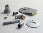
Described is an assembly that can be left in situ, or quickly attached whenever the need arises, photo 1. Although mainly intended to replace the need to ‘tap’ the cross-slide until the correct setting is found, by working from a fixed point and using the attachment’s feed screw, an accurate angle may be found more easily.

 
One alteration to the top-slide is the addition of a locating pin, which will engage one of the twenty holes in the quadrant that includes the desired degree of topslide setting. One further modification is to extend the length of the pivot on the underside of the top-slide, to compensate for the thickness of the carrier should it not engage properly with the cross slide.
 

This is only a matter of counter-boring the centre of the pivot point to a suitable depth and pressing the new bush into place. Although not a true quadrant, the word is being used as a name for the carrier, a plate having a geared section to its edge. The quadrant is set between the cross-slide table and the top-slide with the locating pin set into one of the holes. The feed screw engages with the geared section of the quadrant to give a fine adjustment within the chosen sector, prior to locking the top-slide. A single screw on the front face of the cross-slide secures the feed screw bracket and a locating pin ensures the correct position.

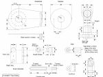
The first item required for the construction of the quadrant, is a spigot, photo 2, the base of which is of a diameter to fit the recess or counterbore of the cross-slide table where the top-slide would normally pivot. A short section of the top of the spigot is also of the same diameter and of a length equal to the gauge of the steel to be used for the carrier plate plus a couple of thou. The middle section is made to fit snugly into the bore of the lathe faceplate.

Article continues below…
Advert

For the quadrant, cut a piece of 18g steel slightly over-size and mark a centre for the pivot point. Set the plate on the faceplate and from the rear of the faceplate, align the mark centrally with the faceplate bore and clamp the two together using three short screws nuts and washers. Place the assembly on to the lathe spindle, drill through and finish using a boring tool until the top of the spigot will turn in the hole without play. While still on the lathe, scribe an arc where the outer edge of the gear is to be fixed. Remove the faceplate and mount it on the index attachment to drill the ring of twenty holes for a locating pin. Remove the carrier plate and deburr the back of the holes.

Cut and bend a piece of 1/8in brass to a close fit with the arc of the carrier and silver-solder into position. File away the excess plate down to the brass, then with the spigot through the faceplate centralise the blank on the faceplate and re-mount on the lathe spindle to take a ‘cleaning’ cut from the brass.

To cut the gear teeth, first set the spigot on a tee bolt, on the cross-slide followed by the faceplate and quadrant, washer and nut and tighten down until the faceplate can be turned without binding, or loosening of the nut. Set a 6mm tap in the drill or collet chuck and feed the cross-slide until the brass of the carrier touches the tap.
 

Article continues below…
Advert
Move the saddle to allow the edge to clear the chuck as the quadrant is turned and lock the saddle. With the drive removed from the pulley, feed the cross-slide on to the tap a fraction, then rock the spindle pulley back-and-forth whilst turning the faceplate in synchronisation, photo 3. After a few passes a shallow thread will have formed on the leading edge of the brass, deep enough to cause the faceplate, if given a little help initially, to ‘self-feed’ along the tap as the spindle is turned continuously.
 
 
A handle fitted to the mandrel would be very useful here but the pulley, (with the smaller drive belt fitted like a tyre for comfort), can be used to do the same job. Continue turning and gently feeding the work onto the tap until, after a few unpleasant ‘crunches and bangs’ (if too much feed is applied), a quite presentable set of teeth will have formed.
 

Photo 4 shows the finished gear, which has been cut to a depth of 2mm,leaving a little under 1mm of thickness at the deepest point.


For the feed screw, a length cut from a long screw was used. The section for the bearing and 5mm thread was turned between centres, for accuracy. The feed wheel dial or control knob is simply a short length of rod, drilled and tapped 5mm at one end for attaching to the feed screw, followed by a lock-nut (turned down from a standard nut). The other end is tapped to take a 6mm socket head screw giving finger control by the knurl. The socket, to take a wrench, is used should the top-slide ever be set at such an angle as to cover the feed screw.

Division marks and numbers are optional and although peculiar will be of a set value and unique to the individual construction. At least one mark will be required when the number of turns of the feed screw is to be counted. Using trigonometry and knowing the total length of the arc to which the quadrant is turned will give a closer value, whatever it may be, to each division.

Article continues below…
Advert
Calculation with the aid of a simple pointer of a set length, with a hole to slip over the pivot point, between the carrier and top-slide can be used to describe an arc. Using this method and a hasty calculation, the length of the arc and the length of the pointer, showed one turn of the feed screw to be equal to 1 degree 25 minutes approximately but, as already mentioned, each individual construction will vary slightly and will need to be calculated independently.   
 
Temporarily clamp the feed-screw in place on the cross-slide and adjust for correct engagement with the quadrant (top-slide in place). Drill and tap, then check the alignment again with the fixing screw in place before drilling for the locating pin. Locating pins and holes are of no specific size providing that they are not too small.
 

As mentioned previously, a 6mm socket cap-head is fitted to the feed-screw dial and is shortened, to leave about two turns of thread, just enough to be able to Loctite and tighten the screw, photo 5. Unless it is intended to keep the attachment in place, then a spacer of the same gauge steel as the quadrant and having a single locating hole, is required, to bring the lathe tool to the correct height without the need for re-adjusting.


Advert

Enjoy more Model Engineer & Model Engineers’ Workshop Magazine reading every month. Click here to subscribe.


Article Tags:

About the Author