Background
I have considered for some time the use of a hand-held turning tool for awkward or final finishing operations on the lathe. I was somewhat put off by the fact that I am a ‘Sinister’ and these operations are awkward left-handed. I can do nothing controlled with my right hand. I even wind a hand drill backwards!
That said it is now time I tried to do it left handed or learn to use my right hand. The first thing was to explore how best to locate the hand rest to support the tool. I have dismissed something held in the Q.C. tool post or on the cross slide, as the rest of the bits would get in the way.
I had a hard look at George Thomas’s device described in his book, ‘The Model Engineers Workshop Manual’. His method was ideal, as it is self-contained and the near instant setup and removal appealed because if something is easily setup it is more likely to be made regular use of. This is borne out by my method of instantly locking the machine vice to the drilling machine table, as described in Scribe a Line, MEW issue 100 p.52. When I now drill anything, the work is always held in the vice and this is always secured to the table.
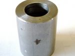
I was going to purchase the Hemingway Kit for this hand rest, when I realised that the base casting would not be suitable for adaptation for my lathe bed, the front shear of which is an inverted Vee form, as with a lot of current lathes, photo 1. The method of locking this rest, together with the fact that the parts remained set when removed and replaced appealed, so I set out to achieve this without the need for the casting or the cam locking arrangement, see the Hand Rest GA.
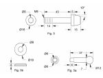
I started with the two clamping pieces, Fig. 1 and found a use for the ability of my bandsaw’s head to swivel 45deg. With the saw set round to 30deg., the first piece cut off was for the shorter clamp. This was then cleaned up on the angled face, as was the angle of the parent bar.
Article continues below…
Enjoy more Model Engineer Magazine reading.
Click here to subscribe & save.
With the two angled faces pushed together, the second piece was marked off to give an overall length of 61mm, the bed centre gap being 60mm.
The base, Fig. 2 has a length of 103mm, being the distance from the rear of the Vee to the back of the rear shear. It could have been shorter, having a rear bearing surface the same as the front, but as I had a piece of material this length, I used it as is.
Article continues below…
The short clamp was marked out and the holes drilled and tapped M8 in the centre and the spring pockets are 7.5mm x 4mm deep on the short face.The base was marked out and drilled 8mm and the spring pockets 7.5mm as before.
The two M6 holes were drilled tapping size at 51mm from the front edge. With the short clamp loosely secured to the base with a bolt, the base was placed on the lathe bed and the longer clamp offered up in its final position. The bolt was tightened to lock everything in place and the M6 holes spotted through to the clamp.
These holes are now tapped, and the long clamp drilled 6mm clearance and counter-bored for the heads of the Allen screws to leave the chamfer on the screw head just proud of the base. Make sure the counter-bores are in the shorter face!
A packing piece is required at the front of the base to make up for the difference in height of the bed. Presumably this varies from lathe to lathe. Mine required a piece of 1.5mm thickness, Fig.3. This was marked out and clamped in position on the base. I used double sided tape initially to hold it while I checked it locked on the lathe bed, then when in the drilling vice, fitted a tool maker’s clamp between the holes to make sure nothing moved.
Article continues below…
The holes were drilled through both parts M3 tapping size to a depth to suit the chosen countersunk screws. I was able to drill, tap and countersink each hole in turn without removing the piece from the drilling machine.
This was cut to length and a centre line marked. The centres of the slot ends and the 6mm hole were marked and all three positions drilled 6mm, Fig. 4. I formed the rounded ends by securing the piece with a 6mm bolt with washers either side, to a block held in the milling machine vice so it could just be rotated. The first pivot is the pillar hole at the end. The free end was firmly clamped in a large ‘Mole’ wrench. The bar is brought up to the side of a 10mm end-mill extending just below the bottom edge so the corners just touch the cutter more or less equally.
The mill is started with the bar well away from the cutter and the table moved to allow the cutter to just graze the first corner and the bar swung to graze the second corner. Back at the start position a cut of 1mm is applied and the table locked in both axes, the bar is swung past the cutter in clockwise direction i.e. into the cut, and returned for subsequent passes until the cutter just contacts each side of the bar.
The piece is then pivoted on the centre hole, and the semi circular end formed to just clean up in the centre. Take lighter cuts and extra care here, as the leverage from the cutting action is much greater.
I have a rotary table and could (Should?) have used that, but this method is quicker to set up and operate and provided a firm grip is maintained on the wrench and the work is fed into the cut, it is quite safe. I have seen websites showing workers performing similar operations by holding the work by hand wearing an industrial glove. Although we are free to do what we like in our own home, I certainly consider this practice to be a definite No-No!
The slot is initially cut with a 6mm slot drill in 2mm steps of depth. With the table at the start of the slot, the slot drill was replaced by an 8mm end mill to finish the slot to size. Again with the table at the start of the slot, a countersink bit was fed down 0.5mm into the work and traversed to the other end. This leaves a pleasing finish to the top of the slot.
A suitable length of material is held in the three-jaw chuck and the entire turning and drilling done at this time. The hole is reamed to provide a nice sliding fit for the hand rest post, and this is where I hit a snag. I have a very good 1/2in. reamer on a No.1 Morse taper, but it is not a machine reamer, it having a significant lead taper. In this type of situation it leaves the bottom of a blind hole tapered preventing the bar reaching to full depth, unless it is also tapered at the end. This is counter-productive, as the fit is lost as the bar is extended. My get round was to drill right through and insert the reamer until its depth equals the length of the hole, remove the work and the reamer and try a piece of the bar material in the hole, seeing how far it is from the end of the hole, ideally about 5mm. If this is not the case, take further cuts until it is. Mount a short length of the bar equal to the thread length required in the chuck, face both ends then drill and tap the required thread.
Article continues below…
This piece is dropped into the hole and with a bolt and washer it is drawn down as far as it will go. Voila! A parallel blind hole with a thread at the bottom, Fig.6.
Hold the piece horizontally in the milling vice with the shoulder just clear of the sides of the jaws, align a slitting saw with the centre of the hole and slit right across keeping just clear of the shoulder. Turn through 90deg., setting the previous slot vertical with a square, and cut the other slot. Clean round all the slots with a square Swiss file
These are straightforward turning jobs as per Fig.5. The handle is up to personal choice as long as it is short enough to allow complete rotation with the arm in place. My stubby handle was chosen because it was left over from another project. It should be placed so it faces towards the tailstock at about 45deg. when fully tightened.
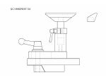
The item produced by George Thomas in his book certainly is of a pleasing appearance, but in a fit of idleness I was put off by all the profiling by mill and file, so I tried a different approach. Fig7.
A short piece of bar of the finished diameter was faced to the required length and chamfered on both ends. A small centre drill was used to just touch and leave a small mark in the centre. The piece was removed from the chuck and with a scriber resting in the centre mark, a rule was brought up to touch the scriber and a deep line scribed from the centre to the outer edge. At 3mm from the centre, a punch mark was made on the line.
Now boring the offset hole calls for holding in the four jaw chuck, but with the idleness still prevailing, I set one of the jaws of the three jaw horizontal facing forward and inserted the blank with the outer end of the scribed line in the centre of the jaw. The jaws were opened until a short piece of 3/16in. Dia. material could be inserted between the jaw and the work, parallel with the chuck face and the jaws gently tightened. A check was made that the punch mark was running true and the face of the work was even with the tips of the chuck jaws before finally tightening the chuck.
The piece was centred and drilled 6mm, opening the hole in 2mm stages until 13mm, which was my largest drill below the 16mm required. With hindsight, and having a 16mm drill, I should have made this part first and turned the spigot on the pillar to suit, but the idleness didn’t set in until I got to this part! However, the hole is opened up with a boring bar to be a firm push fit on the spigot of the pillar.
The piece is now held in the milling vice with the scribed line level with the top of the front jaw. I don’t have sophisticated centre-finding equipment so a point was held in the milling chuck and aligned with one side of the collar. The table was moved 5mm until the point now located the centre of the width and this axis locked. The chuck was moved clear and the point replaced with a 6mm end mill. This being lowered level with the top of the vice jaw and just touching the outer edge of the collar.
With the cutter withdrawn, the table was moved 7mm towards the cutter in the other axis and a stop locked to keep this position. The cutter is fed to the stop from the side in 2mm steps of down feed until the end mill is cutting its full diameter, this axis is then locked.
The end mill is replaced with a centre drill and a shallow centre made. Then drill tapping size for M4 to a depth just short of breaking through. Follow with a 4mm drill to a point 1mm below the scribed line. The tap can be started at this stage if possible but the clearance hole should provide guidance for hand tapping.
When the tapping is completed, the piece is again set in the vice with the line horizontal, this time with the line clear of the side of the vice jaws. Holding the piece at the extremities of the jaws, a piece of packing equal in thickness to the work is placed at the opposite end and the jaws tightened.
Align a small slitting saw central with the line, making sure it will be clear of the vice jaws whilst able to break through into the bore. Form the slot and clean up all round the slot with a square Swiss file. Fit on the spigot, insert the piece of bar for the post and test the clamping action with an Allen screw.
This turned item, Fig. 8 is quite straight forward and requires little comment. The handle is up to personal preference again, but I find small taper pins ideal in this situation. Having exhausted the stock I acquired many years ago and being unable to find replacements, I have come up with a way to mass produce two sizes I can use, and as these are ‘in stock’ it is a quick way to provide such handles. The position for the handle is found by fitting the screw and tightening it with pliers. Use soft packing between the jaws and the work and pull up the screw until the bar is fully locked in the pillar. A mark is made on the screw to leave the handle pointing down at about 45deg. when fully locked.
This is made from 3/4in. square bar as 5/8in. x 3/4in. seems to be unavailable from my sources. There are probably better/ easier ways to produce this item, but I am quite pleased with the final result using this method, Fig. 9.
First mark and drill the 9mm hole then scribe the four longitudinal lines on the piece ready for removing the unwanted material. There then follows a pause while you figure out how to hold it with the area to be formed horizontal, with only the ends as parallel gripping faces. It could of course be set on packing gripped by the ends, but the gripping area gets quite a bit smaller as work proceeds.
The method I chose utilises the horizontal Vee in the milling vice’s moving jaw to provide one secure location leaving just a corner to bear on the fixed jaw, which means if anything is going to come adrift, it will be here. My thoughts were that under the influence of the cut, the likely direction would be downwards. So the first pair of lines were carried round to one end and these marks joined with a marker pen for visibility.
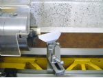
The work was set in the vice as described with the marked line on the end horizontal. A piece of round material is used to fill the triangular gap underneath, the size found by trial using twist drill shanks as these are in many more sizes than bar stock. My M12 tapping drill was just right at 10.3mm, photo 2.
The unwanted material was removed with a 12mm end mill. The next pair of lines is set horizontal and the process repeated. The next step is removing the waste from the 35deg. sloping sides. This really was a challenge to hold and perform by mechanical means, so I didn’t.
With a protractor set to the angle, and working on the face as drawn in Fig. 9, the base was held against the top edge with the blade lined up with the end of the earlier scribed line as seen on the sketch. Another felt tip line was drawn down this face to the bottom edge and this line carried round the top edge to produce a line on the end parallel with the top face. This was repeated for the other side.
With the marked face flat against the front jaw of the bench vice, the vice was nipped up to leave the marked line vertical against a square resting on the vice jaw and the bottom of the line just above the jaw. The vice is tightened and looking at the line marked in the end, which is sloping at an angle in two directions, start the hacksaw on the upper corner and gently start cutting with the blade following both lines. This requires some patience at first, but once you get used to holding the saw at a weird angle to the vice, the job is soon finished. The marking for the other side is lined up in the same way and the cut repeated with the saw at a weird angle in the opposite direction. When completed, file out the saw marks and treat all faces to some draw-filing, remove all sharp edges and rub all over with a Scotchbrite pad.
Now for an easy job, cut the piece to length, face the ends and turn down the small spigot to a press fit in the hole in the rest, Fig. 9 or if into adhesives/ soldering, the appropriate clearance. Gripping the rest in the vice by its ends with the hole vertical tap the post home with a machinist’s hammer to complete this item.
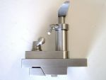
If you have not already done so, put a generous chamfer on the top corners of the base and the support arm, and a lead in bevel on the bottom edges of the clamp block faces. The component parts are now complete, photo 3 and after any final finishing deemed necessary, can be finally assembled and fitted to the lathe, photo 4. It was found that the diminutive locking handle only required about 30deg. of a turn clockwise to lock everything dead tight, and when removed, the springs kept the support arm in its set position. This achieved the desired result of speedy and repeatable mounting.
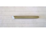
The rest was set in the working position, photo 5 and using a tool made from a piece of 3/16in. square HS steel fitted in a file handle, photo 6 I tested the water with a piece of plastic, photo 7.
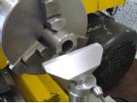
Now confident, it was time for the cold steel! Photo 8. The rest was moved to the internal cutting position, photos 9 and an internal chamfer produced. This is definitely awkward for ‘left hookers’, but as my camera is exclusively right-handed, I had to persist with using the left hand.
I was quite satisfied with my first attempt to clean the edges of a bored cylinder, photo’s 10 and 11, and the ease of installing and setting the hand rest has lived up to my expectations.

Photos 12, 13 and 14 show finished views of the hand turning rest.